Stay Up to Date
Submit your email address to receive the latest industry and Aerospace America news.

The fundamental mathematics that aircraft designers rely on to model fluid mechanics, the Navier-Stokes equations, were devised in the 19th century. This set of partial differential equations seems tantalizingly straightforward, yet many challenges remain today in realizing an accurate predictive capability. Stephen M. Legensky, founder of the software company Intelligent Light, explains.
BY STEPHEN M. LEGENSKY
In my journey as the founder and leader of Intelligent Light, I have had the privilege of meeting some of the pioneers of CFD through our visualization and knowledge-extraction software products. These visionaries freely shared their valuable time, answering my naïve questions and helping me to understand their field and how our tools might help the CFD community. In the late 1980s, United Technologies Research Center used our 3DV software to produce animations of CFD results by converting them into formats that could be rendered and recorded to video tape. Thus began my adventure and a great opportunity for Intelligent Light through our FieldView software, which has helped countless engineers visualize and model aircraft performance by solving the
Navier-Stokes equations, the fundamental mathematics for modeling fluid dynamics that were devised in the 19th century. As powerful as the FieldView tool remains under its new owner, FieldView CFD Inc., much innovation remains ahead to fully tap the potential of applying the Navier-Stokes equations for modeling aircraft in flight.
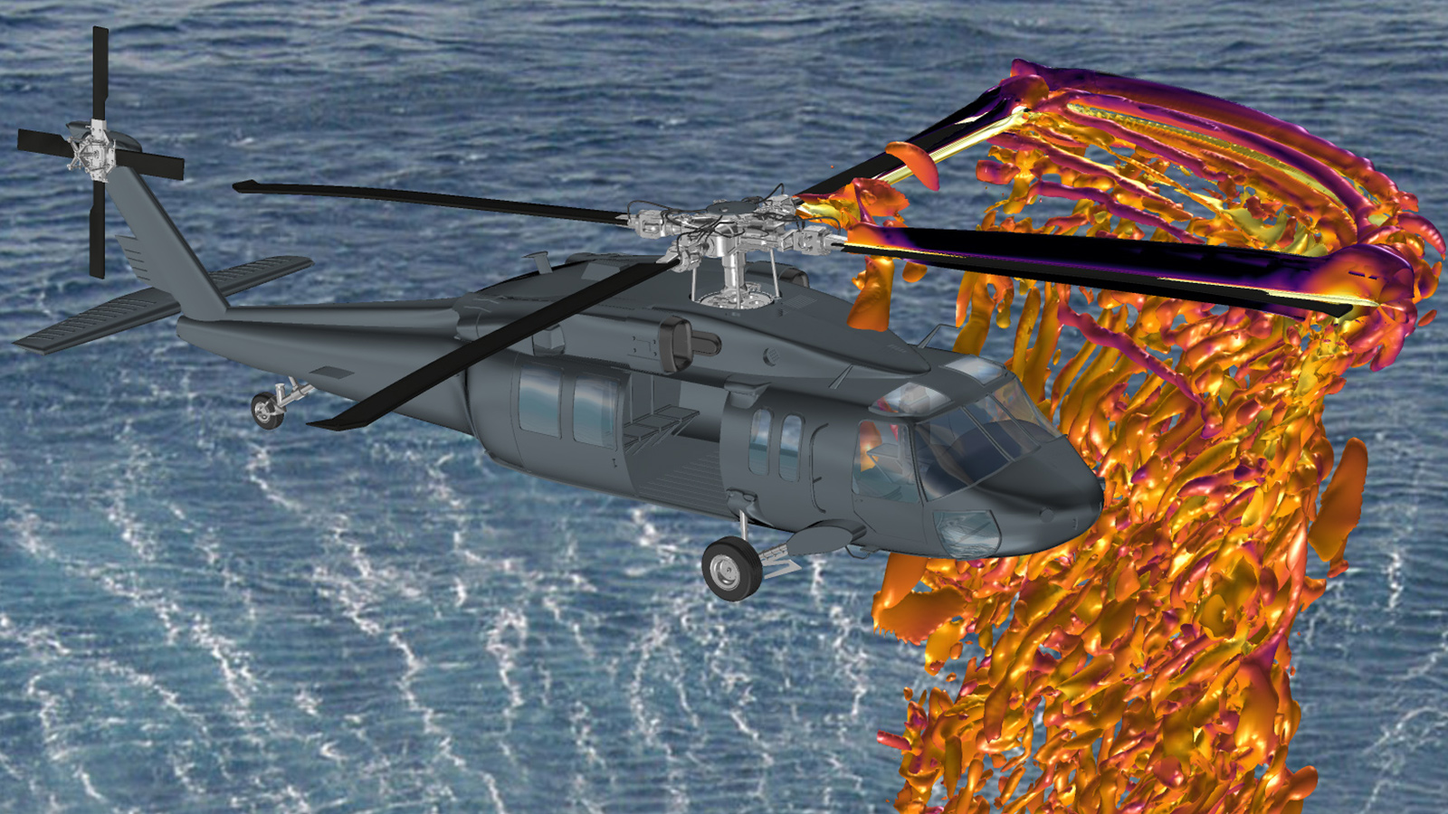
So why are the Navier-Stokes equations so difficult to tame? Unlike static structural analysis and other physical modeling regimes, the Navier-Stokes formulae are partial differential equations that for most interesting geometries and realistic flow conditions do not have an analytical solution. You can’t just plug algebraic terms into the Matlab software and get an answer. Numerical methods for solving these equations have been under development for more than a half-century. The fundamental idea for the most popular methods is to discretize the flow domain around or within the object under study: The physical space is divided into cells as small as a millimeter on a 747-scale aircraft. Time is also broken down into very small timesteps, sometimes on the order of microseconds or even nanoseconds.
Solution methods with names like Finite Difference, Finite Volume, Finite Element and Direct Numerical Simulation are then applied to the millions or billions of cells, timestep by timestep. (Techniques such as Lattice-Boltzmann, Particle-in-Cell and Smooth Particle Hydrodynamics are also used but tend to have more specialized applications.) Each of these methods has advantages and disadvantages in terms of memory needs, computing power requirements, stability (meaning: do we get an answer or a program crash) and most importantly, accuracy.
Solving differential equations has another important requirement: boundary conditions. For example, what is the speed of the airplane or the temperature and pressure at the inlet of a jet engine combustor? These conditions are natural to us in the real world, but expressing them accurately as inputs to the solution program (known as the solver code) or even measuring them accurately can be very challenging. Even if we could manage boundary conditions, discretization and solution method, there is a trade-off between what can be directly solved and what needs to be modeled. Turbulence, the tendency for many flows to exhibit an almost chaotic behavior, exists at many scales and directly impacts lift and drag, supersonic combustion and other phenomena. The quest to understand and model turbulence has been an ongoing pursuit for more than a century.
Moving to uncertainty quantification
Where are we today with CFD and its application to real-world problems? For many years, engineers applied CFD most often to analyze performance trends due to design changes, rather than as a quantitative, predictive tool. If my airplane was not behaving as I expected, CFD might be used to simulate the flow, computing the velocity in each cell in three dimensions around my vehicle so that, with the appropriate software, I could visualize the flow field. If the cause of the problem could not be located, a change could be made to the shape of the wing, and then another calculation would be performed. This was probably much less expensive than modifying the actual aircraft and testing in flight.
Quantitative results could be expected only for certain situations that were well understood with well-behaved designs, such as an aircraft with smooth flight surfaces operating at cruise conditions. These predictions were very important for estimating the fuel efficiency of a new vehicle and identifying the design that was the best compromise. Airframers have been refining the tools and processes for this kind of application for years, but these revisions still do not cover more demanding scenarios. You see, these traditional calculations apply to airplanes that are deliberately shaped to avoid the types of fluid mechanics phenomena that plague CFD even to today: flow that separates from the flight surfaces and might possess unstable vortex behavior. In such cases, the physics of the flow can reveal the shortcomings in the solver code, discretization and turbulence model. But, if you do not know the correct answer for a new design, how does one know if the calculations are truly predictive?
This is where the field of uncertainty quantification comes in. Over the past decades, UQ has gained prominence as a way to understand and to quantify the reliability of analysis predictions. The simplest way to understand the role of UQ is that it provides a rigorous statistical framework to incorporate experimental data, variations in CFD methodologies and boundary conditions into the analysis process. Rather than just stating that the predicted drag will be 107 under particular conditions, the engineer is provided with what are called “confidence intervals” that might read like: “Within a 95% confidence level, the drag is predicted to be between 104 and 110.” Currently, the UQ process can be computationally and experimentally expensive, since instead of doing one simulation with fixed boundary conditions or turbulence models, many such computations are needed to create the statistical picture of the simulation certainty. Creating efficient workflows for UQ is certainly a topic of extensive research today. Intelligent Light has been funded in this area by the U.S. Department of Energy, whose DAKOTA software is the gold standard for UQ and optimization.
Increased precision
Working in UQ is an eye-opening exercise for CFDers. Several sources of uncertainty have been identified in the CFD workflow: discretization, model form and boundary conditions are a few. What were once accepted as good enough are no longer: If you really want to predict the behavior and performance of brand new concepts or you want to understand flow regimes that are not well behaved, then, in reality, the status quo is not good enough. In general, the precision of the discretization has to be increased in order to truly capture the object’s shape and perhaps the turbulent scales. In the emerging concept of the digital twin, geometry is modeled as built, rather than from the idealized computer aided design. Then the boundary conditions need to more closely approximate the real world: Is the Mach number truly exactly 0.85, or is it between 0.82 and 0.87, and subject to some probability distribution? Finally, there are the numerical modeling issues: Are there compromises in the methods of solving the differential equations and handling turbulence? All of this co-exists with limitations on computing resources, solver performance, the workforce and even the ability to gather useful ground truth from tests.
The CFD development community is vibrant today and actively developing new technologies to improve the robustness, accuracy and efficiency of codes that use the various numerical methods. NASA funded an effort to set goals for CFD by the year 2030, and a report was published in 2014. These goals have brought focus to advancing the areas of solver methodology, discretization, turbulence modeling, UQ and also knowledge extraction. An update is due for publication at AIAA’s SciTech 2021; see that white paper for the technical details of the progress being made and the teams that are advancing toward the goals.
For our part, Intelligent Light has been playing a supporting role for the CFD community, focused on UQ, knowledge extraction and data science applications for CFD. One of the problems with the increase in fidelity and the number of simulations is data size. Although supercomputing has scaled in performance by orders of magnitude over the decades, we humans have not. Two interesting aspects of work in this area are extract workflows and solution interpretation guided by data science techniques. Extract workflows attempt to get the most meaningful portions of a CFD solution directly from the solver memory into a compact useful form. Data science techniques, either modal analysis or machine learning, can help to find patterns or coherent structures within the sea of raw data.
It should be clear at this point that CFD, a field of study with a rich history, still has many opportunities for improvement. I am confident that the dedicated practitioners out there in the world will continue to push the boundaries of the technology for years to come. At the same time, machine learning is making strides to complement the current state of the art. I read in MIT Technology Review about a deep learning technique developed at Caltech that can solve families of partial differential equations such as Navier-Stokes a thousand times faster than traditional methods. Stay tuned.
Stephen M. Legensky
founded Intelligent Light in 1984 and remains president and chief technology officer. He helped grow the company from a producer of 3D animations to a leading supplier of tools for CFD workflow and UQ. He has a bachelor’s degree in engineering and a master’s degree in mathematics from Stevens Institute of Technology in New Jersey.
Related Posts
Stay Up to Date
Submit your email address to receive the latest industry and Aerospace America news.