Modeling structural strength
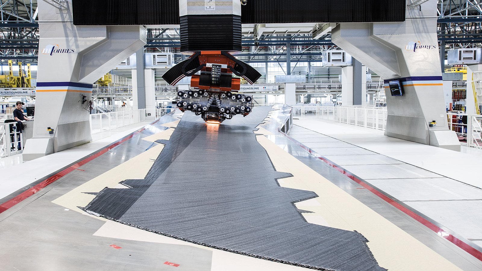
Building the carbon-fiber wing of a Boeing 787 or Airbus A350 starts with a robot arm slung from a gantry and gliding swiftly back and forth over a mold of the wing. The arm whirs and clicks like a PC printer head gliding over a sheet of paper — if the printer were large enough to hold the wing of an airliner. With this technique called automated fiber placement, or AFP, the robot lays down strips of sticky, resin-infused carbon-fiber tape, side by side and then layer upon layer, to build a 3D wing or fuselage structure that later will be hardened in a giant autoclave, a chamber that heats and pressurizes for curing.
Wings built from this robotic method are safety tested for strength and flexibility just as other variations of carbon-fiber wings and aluminum wings were before them: with physical stress tests. AFP robots are capable of building carbon-fiber structures with finely tuned strength and flexibility for specific points in an airplane, which has at least in theory opened up new design possibilities for stronger, lighter aircraft. But the endless structural variations that are theoretically possible from the AFP robots are limited by the cold, hard reality of expensive and time-consuming physical testing that is required for each iteration.
A University of Michigan aerospace engineering professor and a team of colleagues and students are building computer models to predict the strength of carbon-fiber composite wings, fuselages and other aerospace structures made with AFP techniques. If they are successful, airplane manufacturers will have a tool to help them know whether an AFP-made structure is as strong and flexible as designers intended it to be, without having to physically test that structure, opening up new design possibilities for stronger, lighter aircraft.
The professor, Anthony Waas, began developing the computer models about six years ago as manufacturers began making large aerospace structures with the method. An AFP robot can produce precisely the same patterns of carbon fiber every time, repeating the exact same wing or fuselage structure it was programmed to build over and over, and swiftly. While airplane builders are currently employing AFP, airplane designers have just scratched the surface of concepts made possible by AFP for stronger, lighter designs with precise degrees of flexibility or stiffness at specific points within the planes’ structures.
“We will see further and further and further improvements, and we are going to see amazing new capabilities; new designs; new structures; new everything, as time goes on,” Waas says. “You can actually make the structure behave exactly the way you want it to behave for different loads: when it’s in flight, when it’s maneuvering, when it’s lifting.”
Those possibilities are expanding even more with a new variation on the automated fiber placement technique called steered AFP.
To build a large carbon-fiber structure for an airplane, AFP robots typically put down the 3-millimeter- to 1-centimeter-wide strips of tape in straight-line patterns for each layer, often many strips at a time in 20-centimeter-wide swaths with each pass over the mold. To create structural complexity and added strength in a carbon-fiber laminate, a robot might lay down the first layer in parallel strips at a 0-degree directional heading, followed by a second layer set at a 45-degree heading, then minus 45 degrees, then back to 0 degrees, and so on. The skin of a wing root might be made from 150 layers of tape to maximize strength, while the skin of the wing tip might require only 10 layers.
Steered AFP makes even more patterns and structural complexity possible.
With steered AFP, the robot can be programmed to lay down the parallel strips in curves, and therefore engineers can design lighter and stronger wings and other structures, along with added stiffness or flexibility, as the design may require at specific locations. The robot might steer circular patterns around the windows in a fuselage, for example, or for a wing lay down S-shaped patterns that are offset with each subsequent layer to tailor the design for added stiffness and strength.
The expansive possibilities created by AFP and steered AFP techniques presented a problem for airplane builders and the companies trying to sell AFP robots to them: Without software that could reliably predict the strength and flexibility of all these newly possible carbon-fiber structures, each new structure would have to be physically tested. That could be expensive and time-consuming. Waas set out to develop his predictive computer models to solve this problem.
The issue is especially prominent for steered AFP, which is still in the research and development stage for aerospace applications, says Timothy Brooks, a former student of Waas’ and now a research and development engineer in Boston for Nevada-based Aerion Supersonic. “One of the hardest problems you get is that as of today there doesn’t really exist a standard process or procedure for certifying” steered AFP structures, he says.
To move steered AFP concepts from the academic and research realm into large-scale aircraft production, the industry will need computer modeling, which can provide a better understanding of the specific strength, flexibility and weakness of individual steered AFP structures. Predictive computer models would also represent a big step toward certifying aerospace structures for regulators without extensive physical testing, Brooks says.
Currently, traditional AFP is widely used by airplane makers, but “there’s been very little exploration of moving away from that and looking at steered AFP laminates,” Brooks says. “Figuring out how to build confidence in these laminates and predicting a lot of these mechanisms I think is crucially important to getting them adopted in future designs.”
Waas chose a finite element method software called Abaqus, sold by Dassault Systèmes Simulia Corp. of Rhode Island, as the base for the computer models and software that he and his team of five graduate students and postdoctorals are developing. The software determines the strength of a structure, such as a wing, by solving millions of equations quickly. Specifically, the strength of every cell within a mesh overlay of the structure would be calculated, as would the strength of every cell for submeshes within that mesh, and so on.
Waas is adding physics to the software, analyzing how manufacturing defects in the robot-made carbon-fiber structures can fail down to the level of the matrix of interlocking 6-micrometer-diameter fibers. “If you know the details of the microstructure of the material, you can actually predict the strength,” he says.
To predict the strength of a robotically manufactured aviation structure, Waas first has to identify robot-induced defects — the deviations from the perfect intended structure — and show how they affect structural strength. These defects can include points where strips of carbon fiber tape overlap, where ends of tape butt against each other, gaps of varying sizes between two abutting ends, an abutting-end gap in one layer of tape that aligns with a gap in a subsequent layer of tape, and gaps on different layers that nearly align.
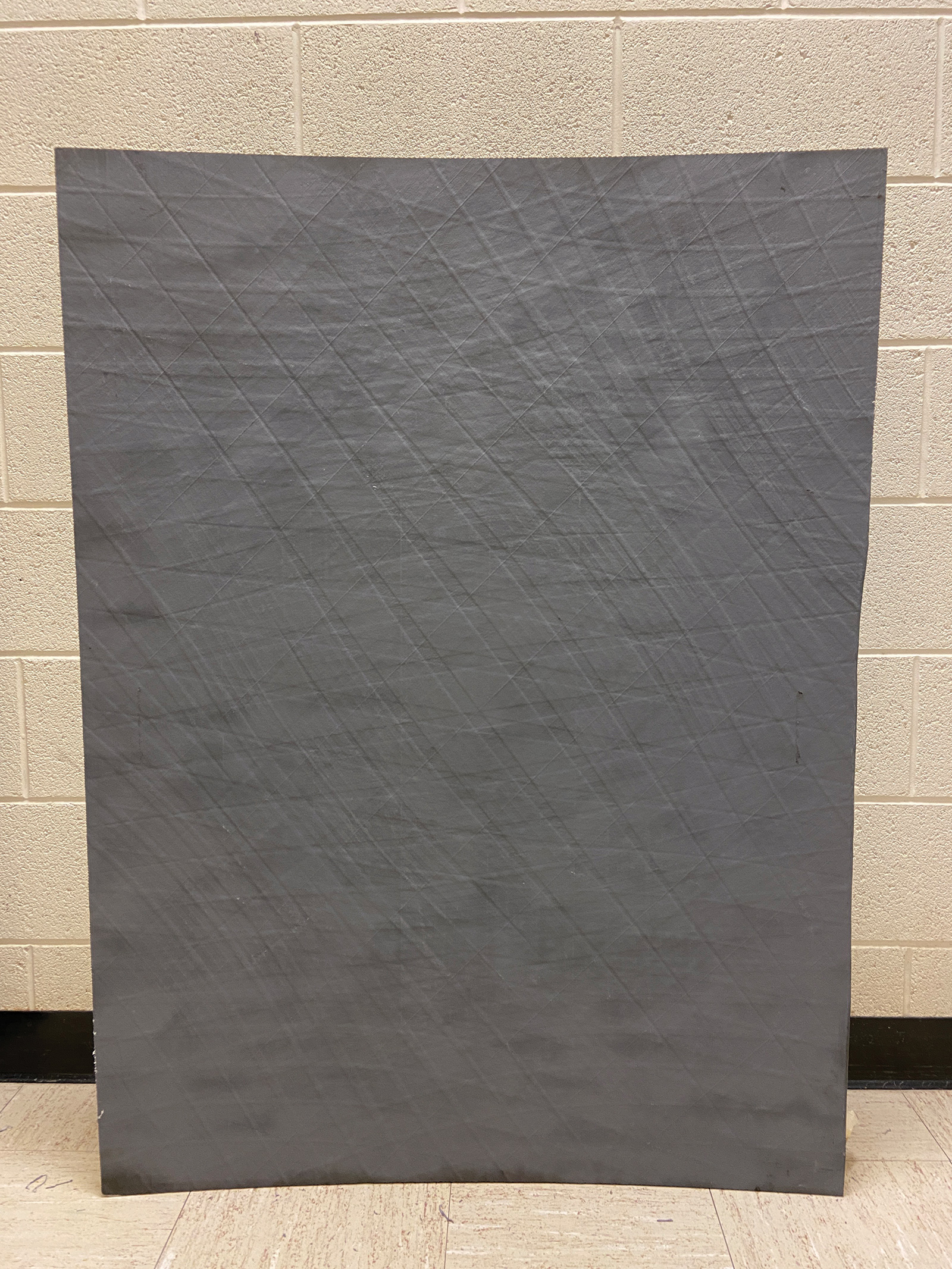
The team has made physical samples of the types of potential defects from carbon-fiber tape, starting with 5-by-5-cm squares a few layers thick, hardened them in an oven, and then tested their tensile and compression strength. For tensile tests, the researchers clamped the samples into test frames powered by hydraulic pistons and gradually pulled them apart, measuring the strain leading up to the sample breaking and recording the cracking and breakage with high-speed cameras. The setup was similar for the hydraulic piston-driven compression tests. They compared the samples with defects to samples without defects and found that the degree of structural weaknesses caused by the defects depends on their type and distribution in the carbon-fiber samples. Also: Some of the defects actually add strength to the carbon-fiber laminate.
The team of engineers plans to test larger samples with more layers and more variations on the defects. In the latest testing, they examined 46-cm-wide squares. Next, the team will move on from testing small pieces of structures to larger pieces and then whole structures. The team has about 15 engineers working on the project, including the Michigan team, University of Texas at Arlington assistant professor Paul Davidson, representatives from two AFP robot makers — Electroimpact of Washington state and Spain-headquartered MTorres — and Japan-based carbon-fiber supplier Toray Industries.
Once the defect types and their effects on structural strength are cataloged and factored into the computer models, the models can take the defect “signature” of an individual AFP robot and precisely predict the strength of the carbon-fiber structures it will produce, Waas says. The robot’s signature is predictable in a given structure it is programmed to make because the robot will do the same thing every time.
“The signature contains all of the types of imperfections that you might run into, and there aren’t many; it’s countable,” Waas says. “The robot does a fantastic job; it really is very precise. But it can be precisely incorrect, or precisely off by a certain factor.”
The next steps for Waas’ team include validating the software with larger and more varied carbon-fiber structures, which involves making, breaking and analyzing many, many samples, he says.
“It takes time; this is done by hand by the students and post-docs,” Waas says. “It’s not easy push-a-button-and-the-results-come-out. It’s a process.”