These researchers are vying to lead the way in the design of rotating detonation engines
A turbine engine must generate a uniform flow of combustion gases to spin its blades without excessive wear or risk of damage. A conventional turbine engine avoids damaging spikes in temperature and pressure by allowing the volume of gas to expand, which encourages even deflagration, the term for the rapid burning of the fuel-air mixture as it’s sprayed or injected into the combustor. The resulting stream of combustion gases rushes through the engine, spinning turbine blades before it exits.
Aerojet Rocketdyne’s Advanced Programs-Rocket Shop in Alabama is working on a radically different combustor design, one that would release energy in a rapid, continuous succession of detonations set off by shockwaves rotating inside a cylindrical combustor. Less fuel would be burned to turn the blades at a given speed, but the engineers must avoid subjecting the turbine blades to fluctuations in temperature and pressure that could damage them or wear them out too soon.
Aerojet Rocketdyne has until June 2019 to demonstrate on university test rigs that its ideas for a rotating detonation combustor can meet that challenge. If all goes as planned, researchers will demonstrate pressure gains and characterize the flow upstream, which would be critical steps toward developing a rotating detonation combustor that could be slid into a power plant turbine. That feat could, in turn, point to a version for jet engines someday.
The company is developing components of the combustor under a $6.8 million, three-year contract with the Energy Department’s National Energy Technology Laboratory. The team is among others in the U.S., plus China, France, Japan, Poland and Russia that are experimenting with designs for combustors that would turn conventional engine designs into rotating detonation engines.
Conservatively speaking, a rotating detonation combustor, or RDC, should reduce specific fuel consumption by about 5 percent compared to a conventional engine. This measure of fuel efficiency is calculated by dividing fuel consumption by power output. A rotating detonation engine generates more power, which drives down specific fuel consumption. A reduction on the order of 5 percent would be a breakthrough, given that designers of conventional engines “try to eke out fractions of a percent,” says Scott Claflin, director of advanced concepts at the Rocket Shop, Aerojet Rocketdyne’s innovation organization.
The key advantage of detonation combustion is that it generates pressure gain in the system, compared to the pressure loss produced by deflagration combustion. RDC designers aim to capture as much of that gain as possible, so that more energy is wrung out of a given amount of fuel, Claflin says.
Detonation vs. deflagration
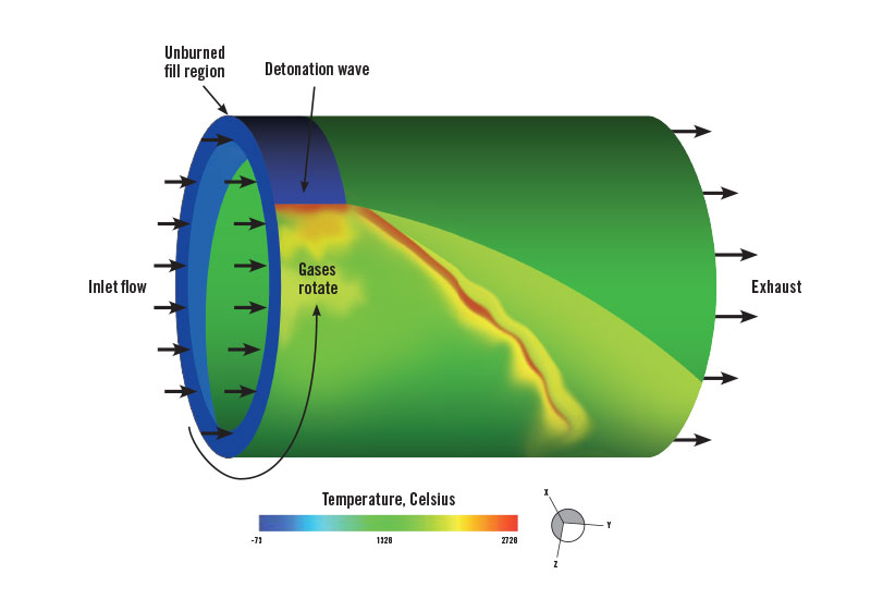
Detonation combustion needs to occur in a space where its volume remains constant, which is why the design is cylindrical; in deflagration combustion, the volume of the combustion has room to expand. The knock in a poorly tuned car engine is an example of deflagration turning to detonation. In an RDC, the combustion starts out as deflagration but quickly turns to detonation. There are variations, but in a baseline design, the compressed air and fuel mixture enters one end and collides with a rotating shockwave produced by the previous detonation. The fuel-air mixture starts to deflagrate but then quickly detonates, producing shockwaves that propagate in opposite directions. These waves travel around the inside wall of the cylinder at 2,000 meters per second, meeting each other from opposite directions and bouncing off each other to reverse direction. Within microseconds, they establish a rotating shockwave moving in one direction that circles the chamber every 0.1 millisecond. The rotating wave slams into the next burst of air-and-fuel mixture entering the combustor, causing it to detonate, and the process repeats itself. There are variations to this baseline approach that involve multiple shockwaves traveling in the same or opposite directions.
Detonation combustion burns a given unit of fuel tens of thousands of times faster than deflagration. This creates pressure spikes with 10 to 1 fluctuations. Deflagration, by contrast, produces a smooth flow field into the turbine with a fraction of a percent variation in pressure and mass flow rate. Conventional combustors “have been designed throughout history to absolutely minimize any pressure perturbations in those devices,” Claflin says.
Introducing unfiltered detonation combustion inside a conventional gas turbine “would be a disaster” largely because of the beating that the engine components would take, says Carson Slabaugh, an assistant professor who leads Purdue University’s contributions to the Aerojet project. “You would want to make that flow as steady and uniform, as homogeneous as possible, to try to improve the life of your turbine.”
Unsteady pressure, temperature and airflow would make thermal management very difficult, especially for the hot sections of the engine. For RDCs to succeed, engineers need to make them produce airflows that are just as steady as conventional combustors. At the same time, the engineers need to make sure that the damping or smoothing of the airflows doesn’t take away their advantage: the pressure gain.
Aerojet Rocketdyne’s engineers designed a device called a diffuser that’s shaped to smooth out the combustor’s airflows as they enter the turbine, Claflin says. “The specifics of how you design the geometry for a rotating detonation engine, no one has ever done that before. So we’re learning for the first time how to design an efficient diffuser for a very unsteady rotating detonation engine.”
Claflin says how the diffuser works is classified, related to Aerojet Rocketdyne’s ongoing work with the Department of Defense. But, he says, the diffuser’s design relies on geometry, not moving parts, to smooth out the pressure and temperature variations.
Aerojet Rocketdyne engineers initially drew lessons from ramjet engines, in which incoming air rams into a structure such as a cone to compress it and slow it to subsonic speeds for combustion, and also from supersonic combustion ramjets or scramjets, in which the air stays at supersonic speeds. These designs require isolators, short ducts between the inlets and combustors that prevent air from backing up and interfering with the incoming air. Researchers tested their diffuser ideas first as CFD (computational fluid dynamics) models, then as scaled-down physical models on test rigs at the University of Alabama, the University of Michigan, Purdue University and Southwest Research Institute. The researchers collected data on the velocities, pressures, temperatures, and chemical species in the flow fields entering and exiting the RDCs.
“If you just do a CFD analysis, you don’t know if it’s predicting reality or not until you have something to compare it against. We’re coming up with the empirical data base that the CFD analysis can be compared against,” Claflin explains.
Currently, the Aerojet Rocketdyne engineers are on their third iteration of their diffuser. They want to see how it performs as they scale it up, Claflin says. They plan to test a 36-centimeter RDC with a diffuser in May at Purdue. By the time the project wraps up in 2019, they plan to test 50 percent scale model RDCs with diffusers that are about 50 centimeters in diameter.
The engineers are also concerned about how shockwaves in their rotating detonation combustor might interact with the compressor, blades upstream of the combustor that compress incoming air before combustion. They don’t want to allow pressure pulses from the detonations in the combustor to move upstream into the compressor, which could disturb the compressor flow or even reverse the direction of the airflow, says research engineer Donald Ferguson of the National Energy Technology Lab in Morgantown, West Virginia.
“You can imagine if you’re generating even a controlled detonation inside that combustor, that the resultant pressure pulse that comes from that wants to go in all directions,” Ferguson says. “We want to contain that with a nonmechanical valve of sorts.”
As with the diffuser, the engineers are developing a nonmechanical solution that relies on geometry. This concept is considered critical military technology so details are not releasable, Claflin says.
Once the current project is completed, Aerojet Rocketdyne’s next step would be to integrate a full-scale RDC into an operational turbine engine, Ferguson says.
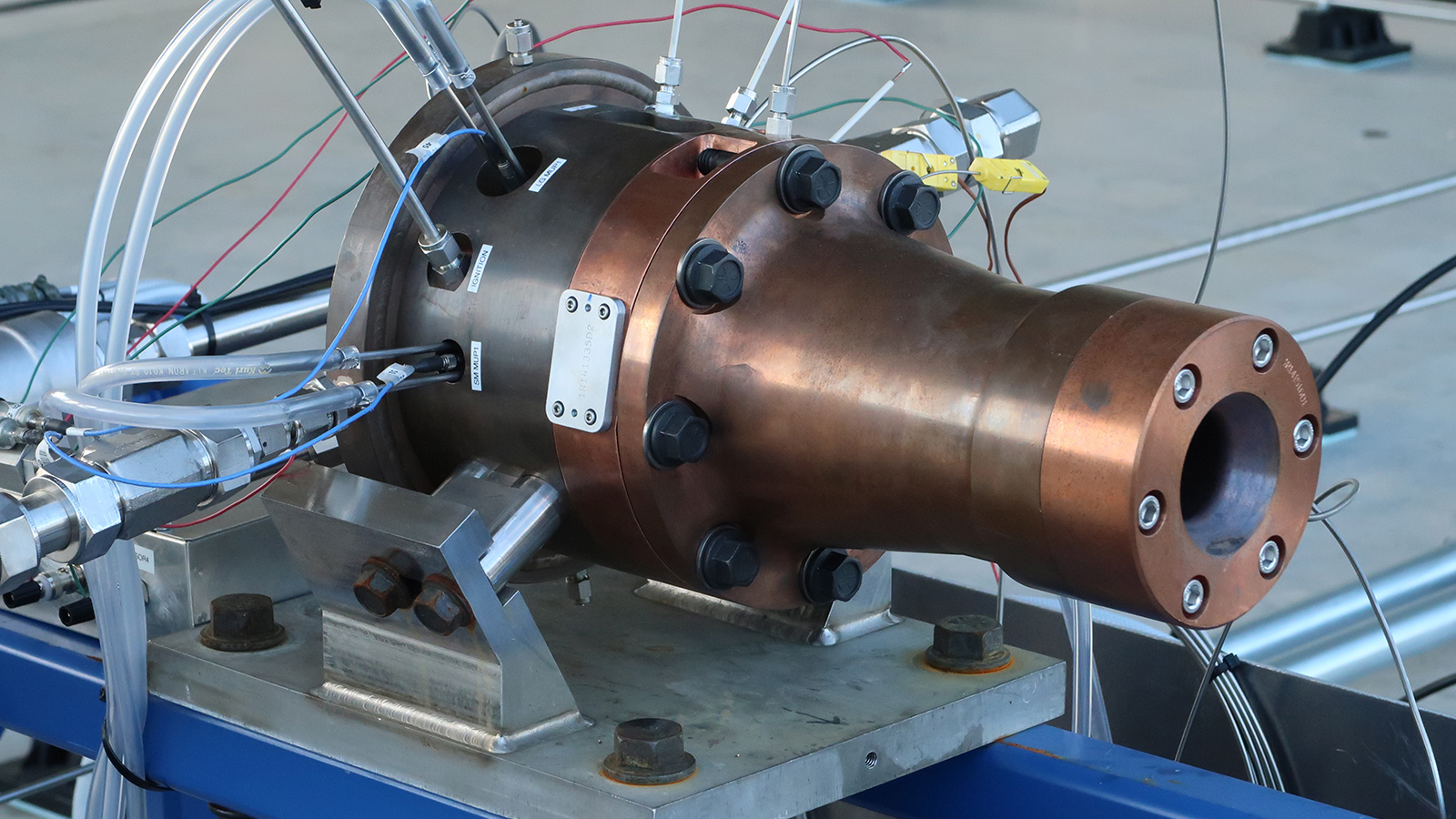
In the Aerojet Rocketdyne photo at the top of this page, a subscale rotating detonation engine is tested at the Southwest Research Institute in San Antonio, Texas. The 10-centimeter-diameter rotating detonation combustor is the gray portion of the machine. The exhaust comes out of the diffuser on the right.