For Vahana, a study in coping with complexity
Aircraft companies around the world are throwing the old design book away in an attempt to gain an edge in the potentially lucrative urban commuter market. With the advent of lithium ion batteries, designers no longer need to pair rotors to bulky combustion engines whose size and weight crimp design options. Multiple rotors can now be distributed across the airframe to maximize thrust, lift or energy efficiency, and wings can be reconceived.
This design flexibility is exciting to engineers, but it also presents aerodynamic modeling and hardware challenges, especially given all that an urban air mobility aircraft must do. They will need to whisk passengers safely over neighborhoods and to and from vertiports, the landing pads that planners envision erecting in suburban neighborhoods and atop city buildings.
For reasons of economics, the aircraft probably will need to do all this autonomously, which is where the modeling comes in. Flight control software can execute complex maneuvers in a variety of wind and weather conditions only if it has an accurate aerodynamic model to work from.
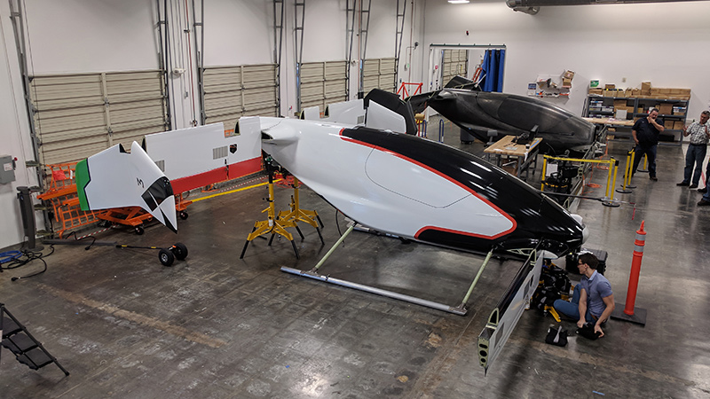
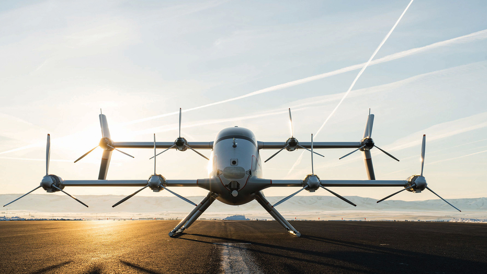
This is the story of how one company, Airbus, addressed that challenge in building and flying its all-electric, self-piloted urban air mobility demonstrator, Vahana. Since 2018, the company has been flying the single-passenger seat demonstrator without anyone aboard in a series of test flights at PUR, the Pendleton Unmanned Aerial Systems Range in Oregon, where the company leases a hangar. The flights could clear the way for development of an operational version that would carry multiple passengers.
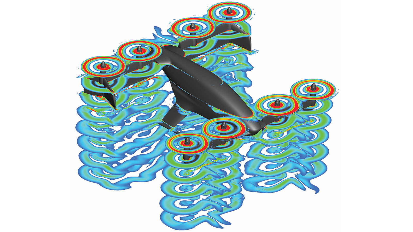
In 2016, when engineers at A³, the Silicon Valley, California, arm of Airbus, received the aircraft design from colleagues, they realized the blueprint was so complex that they could not fully model it with computational fluid dynamics software due to the time and expense, says aerodynamics engineer Monica Syal, a member of the modeling team. Shooting for maximum energy efficiency and safety, designers had created a one-seat passenger cabin with four swiveling wings mounted to it, each with two “fans,” in Vahana parlance, consisting of three rotor blades each. Tilting the wings forward for horizontal flight meant Vahana could achieve a flight speed of 185 kph and demonstrate the ability to turn a 90-minute ground commute into, say, a 15-minute hop. All this would require a mix of 22 different actuators, some mechanical and others electric-motor driven. Two actuators co-located with each of the eight fans adjust the fan speed and rotor pitch; another actuator tilts the front wings and another tilts the rear set. Two more move the elevators on the front wings, and two adjust the position of the ailerons on the rear wings.
If a conventional CFD modeling approach were applied, the CFD would capture the flow physics precisely, but doing so would require approximately 1,000 computations run on expensive high-performance-computing clusters, each run taking two to four days. It would have taken years to complete.
Syal and the other two engineers on her team knew they needed a different tack. Instead of relying entirely on CFD, they decided to first model the main aerodynamic components of the aircraft with medium-fidelity aerodynamics software and turn to CFD only to verify their results. The medium-fidelity software makes certain assumptions to reduce the computational complexity while still producing a reasonably accurate model. With this software, they calculated what the optimal actuator settings would be at hover, at 50 meters per second forward airspeed, and at every 5-meter-per-second increment in between, during the transition between vertical and horizontal flight. As the aircraft moves from full hover to forward flight, the wings must gradually tilt forward, from pointing straight up to flat. During the transition, as the wings are partially tilted forward and fans begin to provide some forward propulsion, the fan-wing combinations set up complicated aerodynamic forces. At a moderate speed when the wings are a third of the way tilted forward, for example, the wings would create significant drag and stall conditions along areas of the wings where no airflow was provided by the fans. But at the same time, on areas of the wings where the fans were blowing, the wings would be producing lift.
This all had to be modeled accurately for the flight control software. The optimal settings were those that would conserve the most electricity while still empowering Vahana to stay in control during unpredictable flight conditions, such as wind gusts or the loss of a fan. Each of more than 1,000 calculations by the medium-fidelity software took 30 to 60 minutes to compute on a desktop computer.
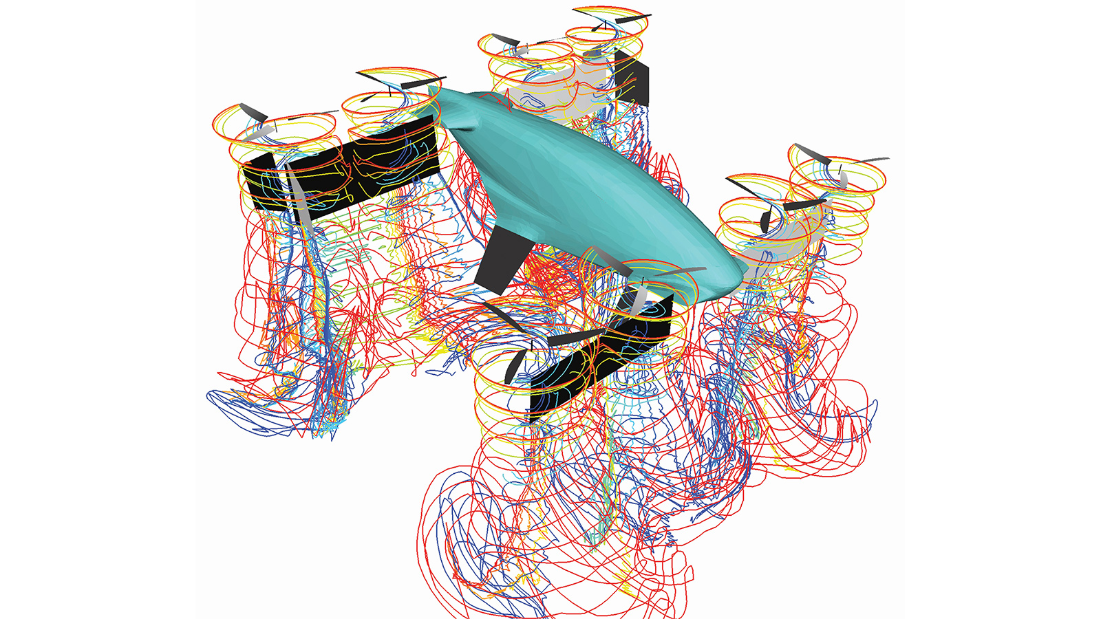
Syal’s team checked the medium-fidelity aerodynamics models for various flight speeds by running the results through the CFD software. The CFD program confirmed their models in hover, low-speed transition and near-cruise flight. For the middle of the transition phase, the CFD software found that the medium-fidelity models hadn’t fully accounted for how strongly the wake from the front set of wings and fans would affect the rear wings and fans. But when the engineers tested the aerodynamics model by flying a quarter-scale Vahana model, they found that the model worked well.
After three months of work, the team in December 2016 completed its first aerodynamic model of Vahana. The model was loaded into the flight control software that guides the 22 actuators to produce lift or thrust through the hover, transition and cruise phases. The engineers tested the model on a computer-simulated Vahana, then by test flying the quarter-scale Vahana starting in 2017 at a site in Hollister, California. Since then, Syal and her team have continued to refine their model with data from flights of subscale Vahanas and a full-scale Vahana in Pendleton. The company has a second full-scale Vahana that it has yet to fly.
Driving the complexity was that, in vertical mode, the fans had to provide vertical lift plus control of pitch, roll and yaw, and then in forward flight, propulsion like an airplane’s propellers. Designers had determined early on that the fan rotors would have to be able to vary their pitch, meaning the angle at which they cut through the air, to lift the aircraft in hover mode and to propel it during forward flight. Fixed-pitch rotors would draw too much electricity when maximizing thrust, says Evan Frank, a mechanical engineer in charge of propulsion for the aircraft.
Most helicopters and turbo-prop airplanes control their blade pitch with hydraulic pumps and hoses powered the aircraft’s combustion engines. But hydraulically powered rotor pitch actuators would have been impractical for the Vahana.
“You can just imagine the complexity of running eight sets of hydraulics out to the wings,” Frank says. “It would drive the takeoff mass of the vehicle up significantly.”
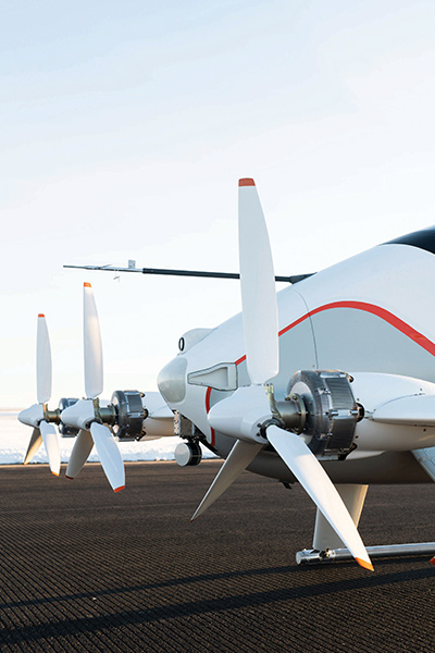
Frank and his team created electro-mechanical actuators, one for each fan, to control the pitch of the three rotors on each fan. Each actuator is 10-by-10-by-20 centimeters, weighs about 1.5 kilograms and is mounted behind the motor that spins the fan. Inside each, an electric motor drives a series of gears and a ball screw that controls the position of a rod that changes the pitch of the rotors. As the aerodynamic models for the Vahana were tested and tuned, engineers refined what they call the schedule for how the rotors would be pitched at various flight speeds. In hover, when the fans are pointed straight up, the actuator pitches the rotors to nearly zero degrees, meaning the rotors cut through the air at a minimal angle. This maximizes thrust, which is essential given that the wings are not contributing lift. After the transition to horizontal flight, when the maximum cruise speed of 185 kph is attained, the fans point straight ahead and the actuator pitches each rotor to a 25-degree angle relative to the air flow so that it chops lots of air. All told, this produces less total thrust than during hover but maximizes forward propulsion. In between hover and cruise, the rotor pitch changes on a continuum that coincides with the forward speed of the aircraft at every 5-meter-per-second increase in forward speed, as does the wing tilt.
Engineers had another challenge. To control the aircraft properly, they had to be sure that each fan would produce the expected level of thrust. While each unit was manufactured within acceptable tolerances, tiny differences in the width or weight of the rotors, for example, would mean that the thrust of one fan at a given RPM might differ by as much as 15% from another fan at the same RPM. That could mean disaster for the software trying to control the Vahana’s flight.
To ensure that each fan produced the same amount of thrust at a given RPM, Frank and his team had to devise a method for testing and adjusting the fans and their associated motors and actuators before they were bolted onto the wings. Engineers decided to bolt these fan units one at a time to a welded-steel frame and measure each unit’s thrust at various RPMs and rotor pitch angles. They then adjusted the software controlling the actuators to produce the same thrust at a given RPM as another fan’s zero-degree setting, for example, at the same RPM. More tests were done to make sure the adjustments worked. After the fan units were tested and adjusted, they were bolted onto the aircraft.
Airbus has moved the Vahana program out of A³ and into the urban air mobility unit that it launched last year to develop UAM vehicles, vertiport concepts and air traffic management ideas. Syal and Frank and their teams plan to fly the Vahana through a complete transition to cruise flight, which begins at 167 kph, later this year.