

Novel concepts for aircraft electrification are introducing the most profound technological changes in the aerospace industry in decades. In this context, batteries play a key role for storing energy onboard aircraft. In-depth testing of battery systems using hardware-in-the-loop test environments is essential for ensuring reliable and safe aircraft operation.
Different types of battery chemistry have been used for aerospace applications in the past. Thanks to recent technological advancements that have led to an increase in performance metrics, the industry is currently focusing on the application of lithium-ion batteries. This also requires additional consideration of potential sources of error such as functional failure, e.g., as a result of degradation, as well as thermal overheating, e.g., due to overcharging 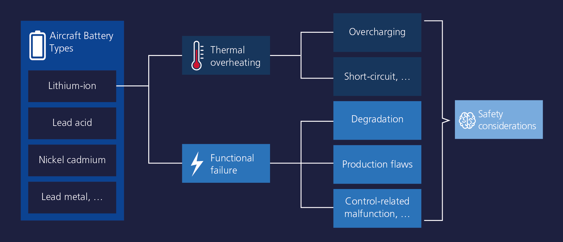 . Consequently, additional safety measures must be established to ensure continuous operation of safety-critical functions onboard aircraft.
To achieve this goal, lithium-ion batteries are controlled by battery management systems (BMS). The BMS continuously monitors the state of health and controls charging and discharging of the battery. Hence, verification and validation tasks must focus on in-depth testing of the entire battery system. A battery system consists of a battery pack and the BMS, whereas the battery pack contains several battery modules, and each module contains several battery cells. The BMS
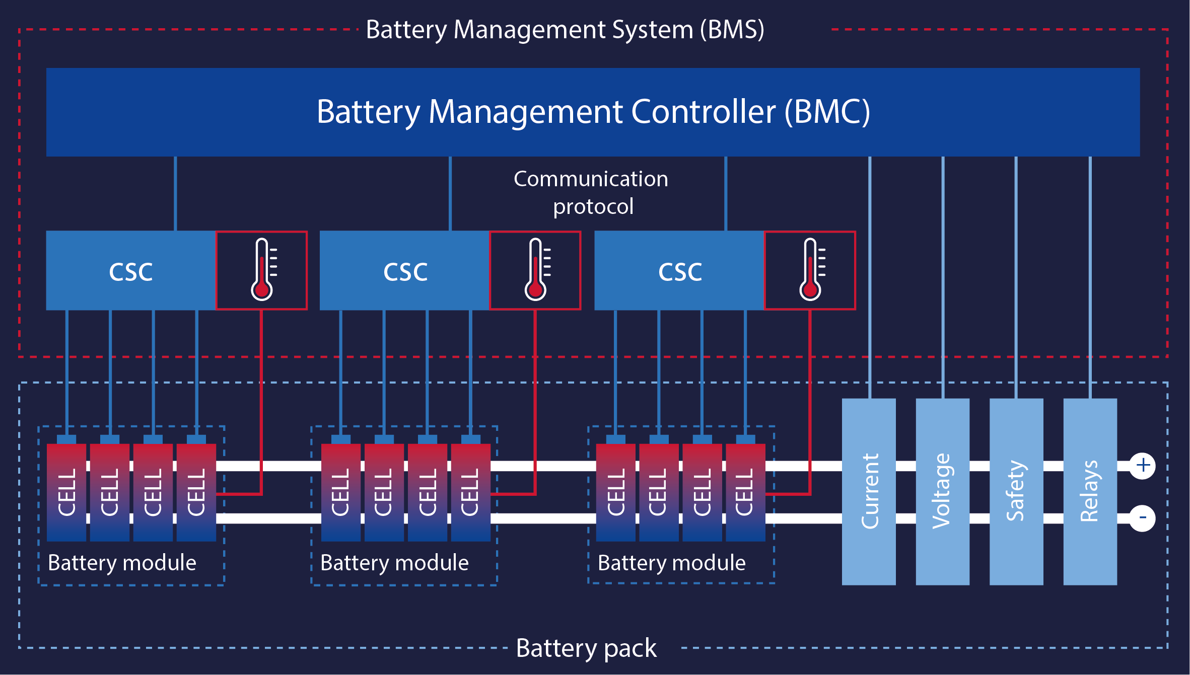
can be divided into cell supervision circuits (CSC) and the battery management controller (BMC). The CSCs are attached to the battery modules to keep them within a safe operating range and perform cell balancing as needed. The BMC serves as the master controller and requests the individual cell information from the corresponding CSCs to monitor the system state of the battery. Based on the information, it determines the state-of-charge (SoC) and state-of-heath (SoH) of the battery. Furthermore, the BMC requests CSCs to start cell balancing, monitors the insulation resistance, and performs the overall thermal and safety management.
Operating Principle of BMS
A multicell high-voltage battery consists of different modules, which are connected in series to increase voltage, or in parallel to increase capacity. The same applies for the design of a battery module. To ensure a safe, efficient, and long-life operation, a battery must be monitored and managed on cell level. Manufacturing tolerances and cell-individual aging may change the electrical inner resistance and energy storage capacity of each cell. To keep the battery within its safe operating range, the CSCs continuously monitor each cell voltage and temperature at different locations. Due to the different charging behavior, some individual cells might reach the maximum SoC earlier than others. Continued charging would lead to overcharging of cells, triggering hazardous failure. Stopped charging would lead to a less efficient utilization of the battery. To prevent both scenarios, the BMS, via the CSCs, balances the respective cells.
Master the Challenges of BMS Testing
Validation of BMS is essential to ensure efficient, fault-free, and safe operation over the entire battery lifetime. Besides testing the functionality of the BMS, it is crucial to verify the safety requirements and overall integration of the BMS.
The test environment must be flexible to enable tests of different BMS. Hardware-in-the-loop (HIL) systems embed the BMS into a battery-realistic test environment to test various battery types, topologies, and cell chemistries. This allows flexible setup of the desired test conditions as a parameter of the battery model. HIL systems enable function tests in early development stages, due to the virtualization of the entire battery. Additionally, they enable electrical failure tests which are only possible under critical battery conditions, increasing the safety of testing. Defects such as faulty cell conditions or faults inside the cable harness can easily be simulated with the HIL system.
HIL tests on BMS can be performed either on signal or high-voltage level. Tests on signal level focus on the BMC software and the communication with the system (CSCs and battery simulated on HIL system). Tests on high-voltage level focus on the complete BMS connected to the HIL system (only battery simulated on HIL system). The HIL system provides the individual cell voltages and outputs for the temperature sensors of the battery, all controlled by the multicell battery model calculated on the processing unit of the HIL system.

Errors that are detected need to be fixed and verified again. The conditions of failed test cases must be reproduced identically to ensure that the errors have been fixed. The HIL tests are fully reproducible and automatable, increasing test efficiency and depth. A typical test solution for testing BMS comprises a HIL system equipped with specific hardware boards to satisfy all I/O requirements and a real-time capable multicell battery model for dynamic simulation of various battery conditions , with high precision and balancing current for cell balancing.
Test Solutions for BMS
dSPACE supports the validation of BMS with pack voltages up to 1,500 V. To ensure safety during commissioning, operation, and maintenance, the test solution includes a central safety controller, isolation monitors, and a safety compartment containing all high-voltage signals. The boards for battery cell voltage and temperature emulation are integrated via scalable battery emulation units as well as all high-voltage and bus signals. This allows for short wiring harnesses and increases the signal quality.
The key component of the system is a cell voltage emulation board which ensures accurate cell voltage generation, down to 300 μV. With the support of peak currents of up to 20 A per channel and high-precision current measurement, the most demanding cell balancing scenarios can be emulated. Each board provides integrated failure simulation capabilities to simulate short circuits and reverse polarity of single cells, open wires between CSC and BMC, and high-frequent disturbance signals. The battery emulation unit integrates seamlessly into SCALEXIO, the individually customizable, market-leading dSPACE HIL testing platform. The low-latency, real-time-capable integration of the cell voltage emulation allows for fast updates, regardless of the number of cells and battery size. Each cell voltage emulation board can be either controlled by the battery model executed on the processor or directly by an FPGA-based application. Any real-time capable battery model based on Simulink® or the Functional Mock-up Interface (FMI) standard can be integrated. The BMS testing solution can be used out-of-the-box with ASM Battery, part of dSPACE’s open, real-time capable, and ready-to-use model simulation library. In summary, the dSPACE BMS testing solution offers a flexible, automatable, and safe test environment, which fulfils the most demanding performance and precision requirements.