
Improving on the ‘gold standard’
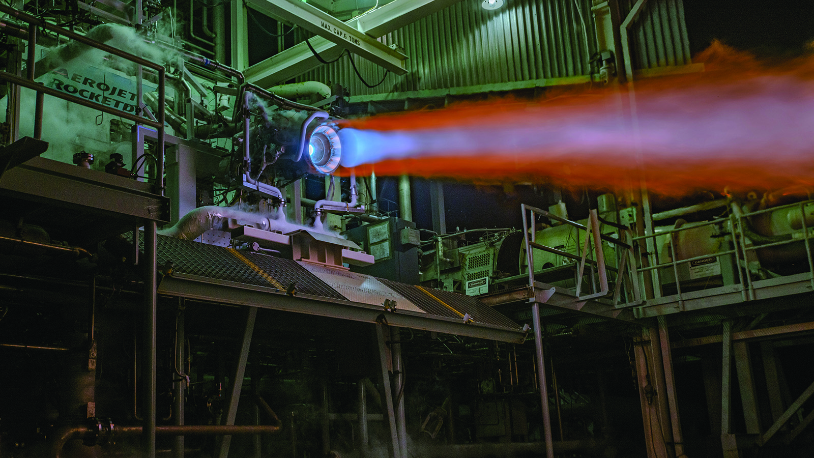
In the swampy woodlands west of Florida’s Interstate 95, the latest design iteration of one of the world’s most famously reliable rocket engines has roared to life repeatedly on a test stand this year as engineers work to qualify the design for its planned debut in space in 2025 on a United Launch Alliance Vulcan rocket.
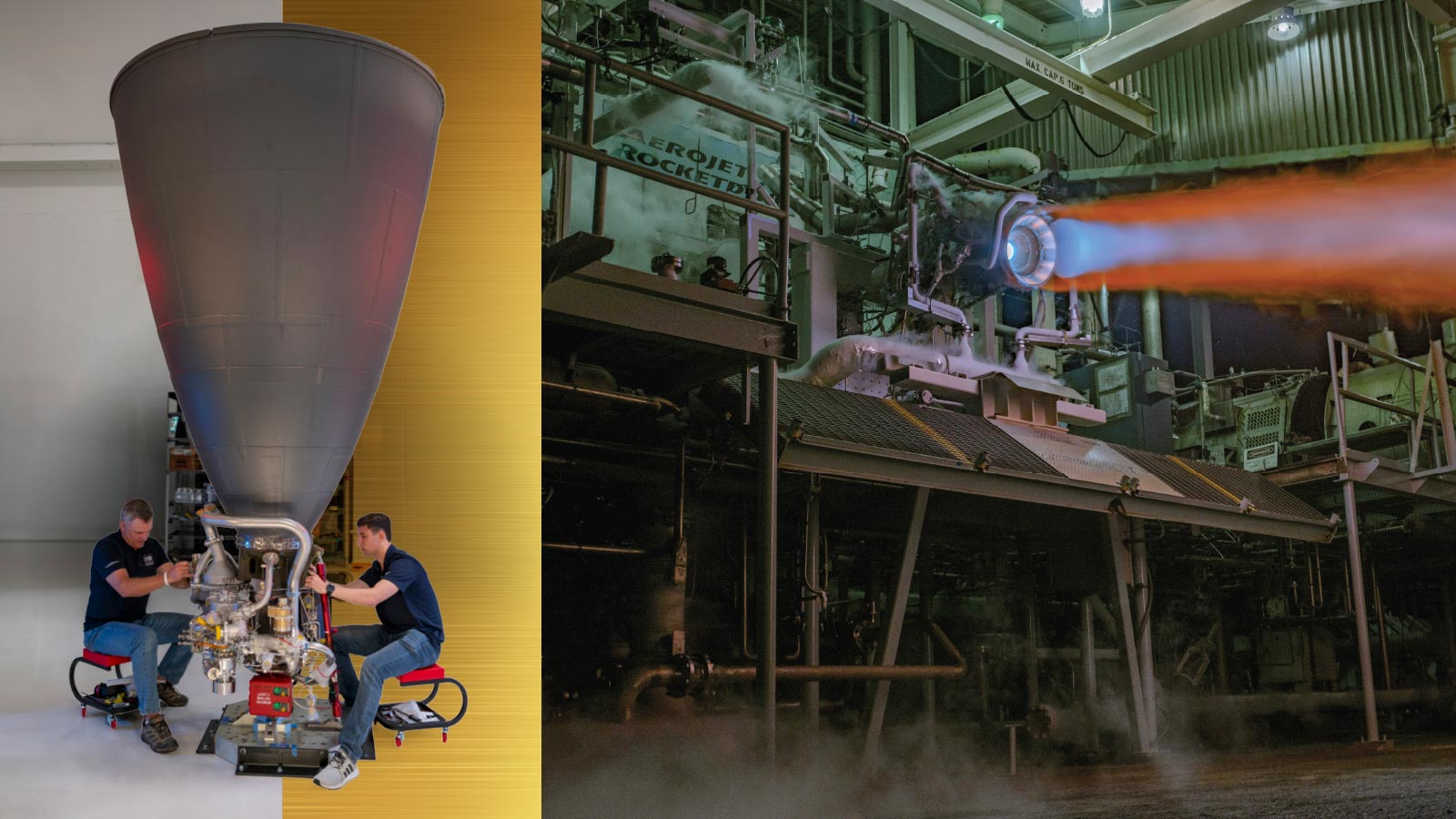
The distinguishing characteristic of this design, known during development as the RL10C-X, is its combustion chamber. Aerojet Rocketdyne additively manufactures them out of copper at its 3D manufacturing division in Daytona Beach, then transports them to the West Palm Beach site where they are assembled into engines and tested. Until now, RL10 chambers have been handmade out of stainless steel.
During each qualification firing, cryogenic liquid hydrogen fuel and oxygen flow from pressurized tanks into the engine. There, the hydrogen flows into hollow channels in the wall of the hourglass-shaped chamber at the top of the nozzle and expands into a gaseous state that drives the turbine for the turbopumps that deliver the hydrogen and oxygen to the injector. This showerhead-like device mixes the oxygen and hydrogen and sprays them into the chamber, where a spark ignites them to initiate a firing that could last 5,000 seconds at 3,200 degrees Celsius.
For this qualification engine to pass, it must perform as specified for at least a cumulative 5,000 seconds over 28 engine starts. That’s “twice as long as the worst-case mission they’d ever see,” says George Prueger, a former semiconductor researcher turned rocket engineer who’s now senior director of RL10 programs. The first qualification engine survived longer than 10,000 seconds, lending confidence that ULA will accept the design.
These hot firings, and the hundred or so others conducted over the past five years, are meant to prove that an updated version of the engines — which once in production will be referred to as RL10E-1s — can be offered without requiring customers to accept more risk.
“The first launch is going to be just like any other ULA launch. There are going to be paying customers on top, I expect,” Prueger says. ULA tells me it expects to make the first launch in mid-2025, but it does not yet know what the payload will be.
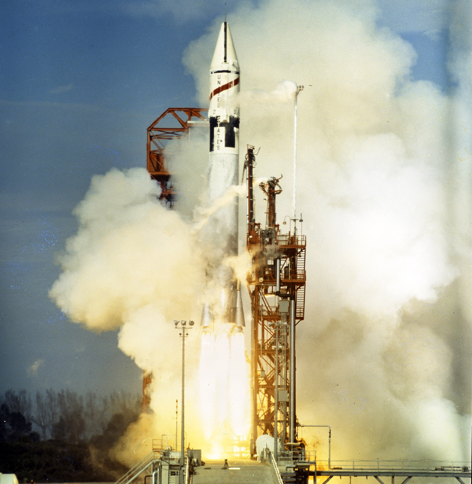
In their role as upper stage engines, RL10s have been trusted since 1963 to boost some of history’s most significant space probes away from Earth and into deep space. There were the Voyager probes in 1977. There was the Cassini Saturn probe in 1997 and the Perseverance Mars rover in 2020. In June, the first crewed RL10 flight carried two astronauts aboard the Boeing Starliner capsule to the International Space Station. RL10s also feature in NASA’s Artemis moon program, with one powering the upper stage of the Space Launch System rocket that in 2022 sent an unoccupied Orion capsule around the moon in the Artemis I mission. The engines have also propelled the U.S. Space Force’s Wideband Global SATCOM and Milstar communications satellites to geosynchronous orbit, along with dozens of commercial and classified satellites. Only one failure has been tallied: In 1999, defective brazing on the combustion chamber wall was the likely cause when an RL10 shut down shortly after the start of its second burn, stranding the Orion-3 communications satellite in a useless orbit.
Why would the company try to improve on such success? About a decade ago, customers began requesting the option of a less expensive version that could be made in less time. For the legacy design, it takes about 20 months to build an RL10 combustion chamber, says Jim Maus, the company’s vice president of space business. Technicians must braze together 360 tubes by hand to form the channels through which the cryogenic hydrogen is circulated to warm and expand it to drive the turbopump and prepare the hydrogen for combustion. Three-D printing with copper has brought that time down to four to six months, and with multiple printers going, now one engine can be delivered per week instead of per month.
The project to deliver that improvement was initiated in 2015, but the engineers did not start from zero. Aerojet Rocketdyne had 3D printed the injector of its RL10C-1-1 engine from Inconel, a nickel superalloy, which provided some experience with additively manufacturing complex components. Armed with that confidence, they set about researching the capabilities of various 3D-printed copper alloys by examining industry databases showing test results. They printed their own flat plates for testing material strength — pulling the samples apart to measure their tensile strength, for example, and heating them to measure how well they conducted heat, verifying the work of earlier materials researchers.
The first printing was done in Daytona Beach in a bed of copper powder enclosed in a tollbooth-sized container. Aerojet Rocketdyne now has six of these 3D printers there. A laser fused the copper to build the first layer of the intended object. Then a thin layer of powder was added to the bed, and the laser fused the next layer of the object, repeating this process until the full object was printed. The printer can be quickly programmed to churn out different shapes, and that allowed for much faster building and testing of new configurations of the chamber, says Prueger, the RL10 senior director.
They found a powder that did the best job of conducting the heat from the combustion to the hydrogen in the walls, and that had the strength to withstand repeated firings. Also importantly, this alloy was readily available and affordable. “We started working down the path of: How do we affect that chamber and not increase the cost or the weight of the engine?” Prueger says. “We really wanted to make sure that we didn’t impact the reliability of the engine.”
One early iteration of the chamber included a bolted-on appendage that would provide additional cooling for the hot gas that would come into contact with the nozzle and would be cooled by hydrogen, but after analyzing the estimated fabrication costs for the part, they nixed it, deeming it too expensive.
Also, after printing, any extraneous copper dust needed to be cleared from the channels. To solve that, they decided to print the two halves of the chamber separately so that the channels could be cleaned out before the halves were welded together.
To test iterations, they fired up chamber test articles on the West Palm site’s “sea level” test stand, so called because it exposes test articles to the open air and normal sea level pressures. That stand is distinct from the “altitude” test stand where the qualification tests are now underway. There, the engine operates in the same ambient pressure that it would experience when fired in space. On the sea level stand, chambers were cycled through multiple starts and stops, measuring the temperature of the hydrogen at various points as it circulated to see how well the copper transferred heat to the hydrogen. Also measured was how well the copper stood up to the extreme temperature swings — from extremely cold in the seconds before ignition to half as hot as the sun at ignition.
This testing pointed to dramatic time savings. Copper’s superior thermal conductivity compared to stainless steel meant that the hydrogen in the channels did not need as much surface area to expand it into the gaseous state required for the rest of the cycle. Therefore, the chamber could be shorter, and shorter meant a higher exit pressure. The pressure is high enough, in fact, that on the sea level test stand the exhaust does not back up into the engine and damage it, as would be the case with a longer chamber.
Today, acceptance test firings on each production engine are done on the sea level stand, which is simpler to operate and maintain. The company describes that as a “key factor enabling our factory to go from delivering roughly one engine per month to delivering one engine per week,” a rate that should be achieved by the end of the year. Only the qualification tests for the design must be done on the altitude stand.
All told, if the new design performs as expected, it could lead to wider acceptance of 3D-printed copper applications across the space industry, says Zachary Cordero, an MIT professor specializing in aerospace materials manufacturing and structures. Because engineers are making changes to a well-established engine, it signals to others in the industry that “they have to have strong motivations” for adopting the 3D-printing method.
“This is the most reliable rocket engine with the most hours of use in the history of spaceflight,” he says. “It’s like the gold standard adopting a technology.”